Búsqueda personalizada
|
| PicManía by RedRaven |
|
Búsqueda personalizada
|
| El lenguaje C es el que uso por defecto para el 90% de mis programas. Aquí os muestro algunos ejemplos de cómo hacer cosas con este idioma. Todos ejemplos que se muestran en esta sección se han realizado usando el C30 (v3.0.2) de Microchip para PIC24H y dsPIC. |
| Índice General: |
|
Lo Hiperbásico: |
|
|
|
|
|
|
|
|
Bailando con Gráficos: La
Librería Gráfica de Microchip. |
|
|
|
|
|
Nota1:
El Micro usado es el dsPIC33FJ256GP710 sobre la tarjeta de desarrollo
Explorer-16 |
| WINK Por donde todo programador que se precie debe empezar. |
|
Este ha sido mi primer programa para un dsPIC. Es un extracto del ejemplo que el mismo C30 trae consigo al instalarlo. Sólo le he añadido la rutina de delay para conseguir el espaciado necesario de los parpadeos del Led. Esta rutina delay (delay.h y delay.c) también la he sacado de otros ejemplos que acompañan al compilador, de todas formas os la pongo completa para que no tengáis que buscar nada de nada. |
/********************************************************************** |
||
| delay.c | ||
|
/********************************************************************* * * Simple Delay Routines * ********************************************************************* * FileName: delay.c * Dependencies: delay.h * Processor: dsPIC33F * Complier: MPLAB C30 v2.01.00 or higher * * Company: Microchip Technology, Inc. * * Software License Agreement * * The software supplied herewith by Microchip Technology Incorporated * (the Company) for its dsPIC30F Microcontroller is intended * and supplied to you, the Companys customer, for use solely and * exclusively on Microchip's dsPIC30F Microcontroller products. * The software is owned by the Company and/or its supplier, and is * protected under applicable copyright laws. All rights are reserved. * Any use in violation of the foregoing restrictions may subject the * user to criminal sanctions under applicable laws, as well as to * civil liability for the breach of the terms and conditions of this * license. * * THIS SOFTWARE IS PROVIDED IN AN AS IS CONDITION. NO WARRANTIES, * WHETHER EXPRESS, IMPLIED OR STATUTORY, INCLUDING, BUT NOT LIMITED * TO, IMPLIED WARRANTIES OF MERCHANTABILITY AND FITNESS FOR A * PARTICULAR PURPOSE APPLY TO THIS SOFTWARE. THE COMPANY SHALL NOT, * IN ANY CIRCUMSTANCES, BE LIABLE FOR SPECIAL, INCIDENTAL OR * CONSEQUENTIAL DAMAGES, FOR ANY REASON WHATSOEVER. * * Author Date Comment *~~~~~~~~~~~~~~~~~~~~~~~~~~~~~~~~~~~~~~~~~~~~~~~~~~~~~~~~~~~~~~~~~~~~ * Richard Fischer 7/14/05 Initial release for LCD support * Priyabrata Sinha 1/27/06 Ported to non-prototype devices * ********************************************************************/ #include "delay.h" unsigned int temp_count; void Delay(unsigned int delay_count){ temp_count = delay_count +1; asm volatile("outer: dec _temp_count"); asm volatile("cp0 _temp_count"); asm volatile("bra z, done"); asm volatile("do #3200, inner" ); asm volatile("nop"); asm volatile("inner: nop"); asm volatile("bra outer"); asm volatile("done:"); } void Delay_Us(unsigned int delayUs_count){ temp_count = delayUs_count +1; asm volatile("outer1: dec _temp_count"); asm volatile("cp0 _temp_count"); asm volatile("bra z, done1"); asm volatile("do #1500, inner1" ); asm volatile("nop"); asm volatile("inner1: nop"); asm volatile("bra outer1"); asm volatile("done1:"); } |
||
| delay.h | ||
| //#define Fcy
14754600 #define Fcy 16000000 void Delay( unsigned int delay_count ); void Delay_Us( unsigned int delayUs_count ); #define Delay200uS_count (Fcy * 0.0002) / 1080 #define Delay_1mS_Cnt (Fcy * 0.001) / 2950 #define Delay_2mS_Cnt (Fcy * 0.002) / 2950 #define Delay_5mS_Cnt (Fcy * 0.005) / 2950 #define Delay_15mS_Cnt (Fcy * 0.015) / 2950 #define Delay_1S_Cnt (Fcy * 1) / 2950 |
||
| WINK2 Igual que el anterior pero con los Led's uno a uno |
|
En el anterior ejemplo
activábamos y desactivábamos todo el PORTA completo, hacíamos parpadear
todos los Led's conectados en la Explorer-16 a dicho puerto. En este nuevo
programa lo hacemos pero uno a uno, comenzando por el PORTA.0 y acabando
en el PORTA.7 |
|
El único truco que hemos utilizado es inicializar una variable a 1 e ir desplazando ese 1 hacia la izquierda antes de sacar el resultado por el PORTA. |
|
/********************************************************************** * © 2007 PicManía By RedRaven * http://picmania.garcia-cuervo.net * * FileName: main_wink2.c * Dependencies: p33FJ256GP710.h * Processor: dsPIC33F * Compiler: MPLAB® C30 v2.01 or higher * * Wink Led Each Port A * * C30 Optimization Level: -O1 * **********************************************************************/ #include "p33FJ256GP710.h" #include "delay.h" _FOSCSEL(FNOSC_PRIPLL); _FOSC(FCKSM_CSDCMD & OSCIOFNC_OFF & POSCMD_XT); _FWDT(FWDTEN_OFF); int main(void){ unsigned int fA; //The settings below set up the oscillator and PLL for 16 MIPS PLLFBD = 0x00A0; CLKDIV = 0x0048; /* set LEDs (D3-D10/RA0-RA7) drive state low */ LATA = 0xFF00; /* set LED pins (D3-D10/RA0-RA7) as outputs */ TRISA = 0xFF00; fA=0x0001; /* Infinite Loop */ while(1){ // Each PORTA to ON LATA = 0xFF00 +(fA); fA = (fA << 1); if(fA==0x0100){ fA = 0x0001; } // Wait 0.5 seconds Delay(Delay_5mS_Cnt * 10); // All PORTA to OFF LATA = 0xFF00; // Wait 0.5 seconds Delay(Delay_5mS_Cnt * 10); }; } |
||
| USART Añadiendo el mas famoso canal de comunicaciones. |
| Otro pasito
adelante. Esta vez le toca a la USART leyendo y escribiendo por el canal
serie. |
| Aquí tenéis un programita que primero se presenta a si mismo, como todo dsPIC de buena familia debe hacer, y después se pone a la escucha del canal serie (por la USART2 que es la que el hardware de la Explorer-16 tiene el MAX232 conectado) y devuelve por ese mismo canal lo que reciba, hace el eco. |
|
/********************************************************************** * © 2007 PicManía By RedRaven * http://picmania.garcia-cuervo.net * * FileName: main_usart.c * Dependencies: p33FJ256GP710.h * Processor: dsPIC33F * Compiler: MPLAB® C30 v2.01 or higher * * Wink Led Port A * * C30 Optimization Level: -O1 * ********************************************************************* * The Processor starts with the Internal oscillator without PLL enabled * and then the Clock is switched to PLL Mode. *********************************************************************/ #include <p33FJ256GP710.h> #include <delay.h> _FOSCSEL(FNOSC_FRC); // Internal FRC oscillator _FOSC(FCKSM_CSECMD & OSCIOFNC_OFF & POSCMD_NONE); // Clock Switching is enabled and Fail Safe Clock Monitor is disabled // OSC2 Pin Function: OSC2 is Clock Output // Primary Oscillator Mode: XT Crystanl char mytext[] ="dsPIC33FJ256GP710 en línea¡\r\nHello TODOPIC (World)\r\n>\0"; void __attribute__((interrupt, no_auto_psv)) _U2RXInterrupt(void){ // Lo que recibo vía UART2 lo pongo en el PORTA ... LATA = U2RXREG; // ... y lo devuelvo como Echo filtrando el 0x0D para añadir 0x0A U2TXREG = U2RXREG; if(U2RXREG==0x0D){ U2TXREG = 0x0A; } IFS1bits.U2RXIF = 0; } void __attribute__((interrupt, no_auto_psv)) _U2TXInterrupt(void){ IFS1bits.U2TXIF = 0; } void InitClock(){ PLLFBD = 38; // M = 40 CLKDIVbits.PLLPOST = 0; // N1 = 2 CLKDIVbits.PLLPRE = 0; // N2 = 2 OSCTUN = 0; RCONbits.SWDTEN = 0; // Clock switch to incorporate PLL __builtin_write_OSCCONH(0x01); // Initiate Clock Switch to FRC with PLL (NOSC=0b001) __builtin_write_OSCCONL(0x01); // Start clock switching while (oscconbits.cOSC != 0b001); Wait for Clock switch to occur while(OSCCONbits.LOCK != 1) {}; } void InitUART2(){ // This is an EXAMPLE, so brutal typing goes into explaining all bit sets // The HPC16 board has a DB9 connector wired to UART2, so we will // be configuring this port only // configure U2MODE U2MODEbits.UARTEN = 0; // Bit15 TX, RX DISABLED, ENABLE at end of func //U2MODEbits.notimplemented; // Bit14 U2MODEbits.USIDL = 0; // Bit13 Continue in Idle U2MODEbits.IREN = 0; // Bit12 No IR translation U2MODEbits.RTSMD = 0; // Bit11 Simplex Mode //U2MODEbits.notimplemented; // Bit10 U2MODEbits.UEN = 0; // Bits8,9 TX,RX enabled, CTS,RTS not U2MODEbits.WAKE = 0; // Bit7 No Wake up (since we don't sleep here) U2MODEbits.LPBACK = 0; // Bit6 No Loop Back U2MODEbits.ABAUD = 0; // Bit5 No Autobaud (would require sending '55') U2MODEbits.URXINV = 0; // Bit4 IdleState = 1 (for dsPIC) U2MODEbits.BRGH = 0; // Bit3 16 clocks per bit period U2MODEbits.PDSEL = 0; // Bits1,2 8bit, No Parity U2MODEbits.STSEL = 0; // Bit0 One Stop Bit // Load a value into Baud Rate Generator. Example is for 9600. // See section 19.3.1 of datasheet. // U2BRG = (Fcy/(16*BaudRate))-1 // U2BRG = (37M/(16*9600))-1 // U2BRG = 240 U2BRG = 240; // 40Mhz osc, 9600 Baud // Load all values in for U1STA SFR U2STAbits.UTXISEL1 = 0; //Bit15 Int when Char is transferred (1/2 config!) U2STAbits.UTXINV = 0; //Bit14 N/A, IRDA config U2STAbits.UTXISEL0 = 0; //Bit13 Other half of Bit15 //U2STAbits.notimplemented = 0; //Bit12 U2STAbits.UTXBRK = 0; //Bit11 Disabled U2STAbits.UTXEN = 0; //Bit10 TX pins controlled by periph U2STAbits.UTXBF = 0; //Bit9 *Read Only Bit* U2STAbits.TRMT = 0; //Bit8 *Read Only bit* U2STAbits.URXISEL = 0; //Bits6,7 Int. on character recieved U2STAbits.ADDEN = 0; //Bit5 Address Detect Disabled U2STAbits.RIDLE = 0; //Bit4 *Read Only Bit* U2STAbits.PERR = 0; //Bit3 *Read Only Bit* U2STAbits.FERR = 0; //Bit2 *Read Only Bit* U2STAbits.OERR = 0; //Bit1 *Read Only Bit* U2STAbits.URXDA = 0; //Bit0 *Read Only Bit* IPC7 = 0x4400; //Mid Range Interrupt Priority level, no urgent reason IFS1bits.U2TXIF = 0; //Clear the Transmit Interrupt Flag IEC1bits.U2TXIE = 1; //Enable Transmit Interrupts IFS1bits.U2RXIF = 0; //Clear the Recieve Interrupt Flag IEC1bits.U2RXIE = 1; //Enable Recieve Interrupts U2MODEbits.UARTEN = 1; //And turn the peripheral on U2STAbits.UTXEN = 1; } void InitPorts() { AD1PCFGHbits.PCFG23 = 1; // This is important. RA7 is muxxed with AN23, // So we need to config the pin as DIGITAL TRISA = 0x0080; // only 0th bit needs be output. A7 is input } void putUART2( char c){ while ( U2STAbits.UTXBF); // wait while Tx buffer full U2TXREG = c; } void putsUART2( char *s){ unsigned int i=0; while(s[i]) // loop until *s == \0, end of string putUART2(s[i++]); // send the character and point to the next one } int main(void){ InitClock(); // This is the PLL settings InitUART2(); // Initialize UART2 for 9600,8,N,1 TX/RX InitPorts(); // LEDs outputs Delay(Delay_5mS_Cnt * 100); putsUART2(mytext); while(1) { // The ever versatile Infinite Loop! Do Nothing } } |
||
|
|
| WINK3 Haciendo uso de la Interrupción del Timer1 |
|
En este nuevo ejemplo vamos ha hacer parpadear nuestro Led pero haciendo uso de la interrupción por desbordamiento del Timer1. Configuramos el Timer1 y vamos acumulando desbordamientos hasta llegar a 500, en ese momento reiniciamos la cuenta y conmutamos (toggle) el estado del Led. |
| main_wink_int_timer1.c | ||
| /********************************************************************** * © 2007 PicManía By RedRaven * http://picmania.garcia-cuervo.net * * FileName: main_wink_int_timer1.c * Dependencies: p33FJ256GP710.h * Processor: dsPIC33F * Compiler: MPLAB® C30 v2.01 or higher * * Wink Led Port A * * C30 Optimization Level: -O1 * ********************************************************************* * The Processor starts with the Internal oscillator without PLL enabled * and then the Clock is switched to PLL Mode. *********************************************************************/ #include <p33FJ256GP710.h> _FOSCSEL(FNOSC_FRC); _FOSC(FCKSM_CSECMD & OSCIOFNC_OFF & POSCMD_XT); // Clock Switching Enabled and Fail Safe Clock Monitor is disabled // OSC2 Pin Function: OSC2 is Clock Output // Primary Oscillator Mode: XT Crystal _FWDT(FWDTEN_OFF); // Watchdog Timer Enabled/disabled by user software unsigned int Count; /* ISR ROUTINE FOR THE TIMER1 INTERRUPT */ void __attribute__((interrupt,no_auto_psv)) _T1Interrupt( void ){ IFS0bits.T1IF = 0; T1CONbits.TON = 0; Count++; if(Count == 500){ Count = 0; LATAbits.LATA1 = ~LATAbits.LATA1; } TMR1 = 0; T1CONbits.TON = 1; // reset Timer 1 interrupt flag } void InitClock(void){ PLLFBD = 38; // M = 40 CLKDIVbits.PLLPOST = 0; // N1 = 2 CLKDIVbits.PLLPRE = 0; // N2 = 2 OSCTUN = 0; RCONbits.SWDTEN = 0; // Clock switch to incorporate PLL __builtin_write_OSCCONH(0x01); // Initiate Clock Switch to FRC with PLL (NOSC=0b001) __builtin_write_OSCCONL(0x01); // Start clock switching while (oscconbits.cOSC != 0b001); Wait for Clock switch to occur while(OSCCONbits.LOCK != 1) {}; } void Init_Timer1(void){ T1CON = 0; // Timer reset IFS0bits.T1IF = 0; // Reset Timer1 interrupt flag IPC0bits.T1IP = 6; // Timer1 Interrupt priority level=4 IEC0bits.T1IE = 1; // Enable Timer1 interrupt TMR1= 0x0000; PR1 = 0xFFFF; // Timer1 period register = ????? T1CONbits.TON = 1; // Enable Timer1 and start the counter } int main(void){ RCONbits.SWDTEN=0; // Disable Watch Dog Timer InitClock(); // This is the PLL settings /*Initialize the Ports All PORTA Output*/ TRISA = 0x0000; LATA = 0x0000; PORTA = 0x0000; /*Initialize Timer 1 for Period Interrupts*/ Init_Timer1(); while(1){ }; } |
||
| ADC & LEDS Un Vúmetro con el potenciómetro y los Leds de la Explorer 16 |
|
Otro primer paso más.
Ahora le toca al conversor AD del dsPIC. En este ejemplo utilizamos el
Potenciómetro conectado a RA5 (el cursor) y sus extremos entre Vdd y Vss. |
| / /********************************************************************** * © 2007 PicManía By RedRaven * http://picmania.garcia-cuervo.net * * FileName: main_adc_volts_for_leds.c * Dependencies: p33FJ256GP710.h * Processor: dsPIC33F * Compiler: MPLAB® C30 v2.01 or higher * * Wink Led Port A * * C30 Optimization Level: -O1 * **********************************************************************/ #include "p33FJ256GP710.h" #include "delay.h" _FOSCSEL(FNOSC_PRIPLL); _FOSC(FCKSM_CSDCMD & OSCIOFNC_OFF & POSCMD_XT); _FWDT(FWDTEN_OFF); volatile unsigned int volts_value=0; volatile unsigned int flag_volts_value=0; void init_clock(void){ //The settings below set up the oscillator and PLL for 16 MIPS PLLFBD = 0x00A0; CLKDIV = 0x0048; } void init_leds(void){ unsigned int i; LATA = 0xFF00; TRISA = 0xFF00; for(i=0; i<3; i++){ LATA = 0xFFFF; Delay(Delay_5mS_Cnt * 20); LATA = 0xFF00; Delay(Delay_5mS_Cnt * 20); } } void init_ADC( void ){ /* set port configuration here */ AD1PCFGLbits.PCFG5 = 0; // ensure AN5/RB5 is analog (Analog Pot) /* set channel scanning here, auto sampling and convert, with default read-format mode */ AD1CON1 = 0x00E4; /* select 12-bit, 1 channel ADC operation */ AD1CON1bits.AD12B = 1; /* No channel scan for CH0+, Use MUX A, SMPI = 1 per interrupt, Vref = AVdd/AVss */ AD1CON2 = 0x0000; /* Set Samples and bit conversion time */ AD1CON3 = 0x032F; /* set channel scanning here for AN5 */ AD1CSSL = 0x0000; /* channel select AN5 */ AD1CHS0 = 0x0005; /* reset ADC interrupt flag */ IFS0bits.AD1IF = 0; /* enable ADC interrupts, disable this interrupt if the DMA is enabled */ IEC0bits.AD1IE = 1; /* turn on ADC module */ AD1CON1bits.ADON = 1; } void __attribute__((interrupt,no_auto_psv)) _ADC1Interrupt(void){ if(flag_volts_value==0){ volts_value = ADC1BUF0; // Save off the RP5 Potentiometer data flag_volts_value=1; // set flag to update Leds } IFS0bits.AD1IF = 0; // reset ADC interrupt flag } void volts_value_to_leds(void){ unsigned int scala,leds; scala = (unsigned int) volts_value * 0x0007 / 0x0C00; leds = scala; LATA = 0xFF00; if(leds>0) LATA += 0b00000001; if(leds>1) LATA += 0b00000010; if(leds>2) LATA += 0b00000100; if(leds>3) LATA += 0b00001000; if(leds>4) LATA += 0b00010000; if(leds>5) LATA += 0b00100000; if(leds>6) LATA += 0b01000000; if(leds>7) LATA += 0b10000000; } int main(void){ RCONbits.SWDTEN=0; // Disable Watch Dog Timer init_clock(); init_leds(); init_ADC(); /* Infinite Loop */ while(1){ if(flag_volts_value==1){ flag_volts_value=0; volts_value_to_leds(); } }; } |
||
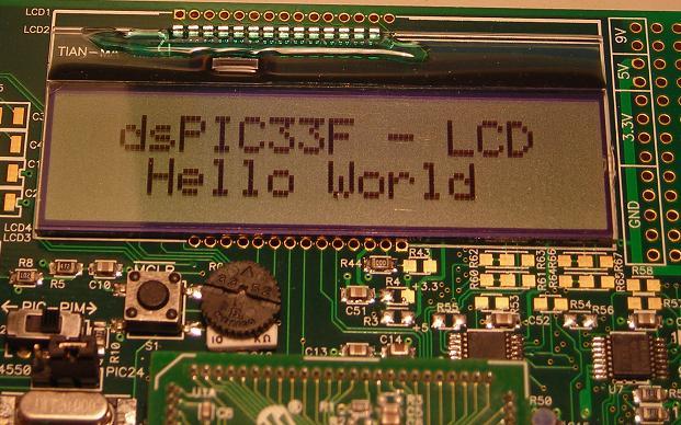
| LCD "Hello World" El LCD mínimo. |
|
Bueno,
continuamos con nuestras pruebas. Ahora el mas simple "Hello Word" en el
LCD. Para ello necesitamos los módulos lcd.c y sus prototipos en lcd.h que
adjunto mas abajo. |
| main_lcd_hello_world.c | ||
/********************************************************************** * © 2007 PicManía By RedRaven * http://picmania.garcia-cuervo.net * * FileName: main_lcd_hello_world.c * Dependencies: p33FJ256GP710.h * Processor: dsPIC33F * Compiler: MPLAB® C30 v2.01 or higher * * Present "Hello World" message * * C30 Optimization Level: -O1 * **********************************************************************/ #include "p33FJ256GP710.h" #include "lcd.h" _FOSCSEL(FNOSC_PRIPLL); _FOSC(FCKSM_CSDCMD & OSCIOFNC_OFF & POSCMD_XT); _FWDT(FWDTEN_OFF); int main(void){ char mytext1[] = " dsPIC33F - LCD "; char mytext2[] = " Hello World "; char *pText1=&mytext1[0]; char *pText2=&mytext2[0]; //The settings below set up the oscillator and PLL for 16 MIPS PLLFBD = 0x00A0; CLKDIV = 0x0048; // Initialize LCD Display Init_LCD(); // Hellow World message home_clr(); puts_lcd(pText1,sizeof(mytext1)-1); line_2(); puts_lcd(pText2,sizeof(mytext2)-1); // Infinite Loop while(1){}; } |
||
| lcd.c | ||
| /********************************************************************** * © 2006 Microchip Technology Inc. * * FileName: lcd.c * Dependencies: p33FJ256GP710.h * lcd.h * delay.h * Processor: dsPIC33F * Compiler: MPLAB® C30 v2.01 or higher * * SOFTWARE LICENSE AGREEMENT: * Microchip Technology Inc. (Microchip) licenses this software to you * solely for use with Microchip dsPIC® digital signal controller * products. The software is owned by Microchip and is protected under * applicable copyright laws. All rights reserved. * * SOFTWARE IS PROVIDED AS IS. MICROCHIP EXPRESSLY DISCLAIMS ANY * WARRANTY OF ANY KIND, WHETHER EXPRESS OR IMPLIED, INCLUDING BUT NOT * LIMITED TO, THE IMPLIED WARRANTIES OF MERCHANTABILITY, FITNESS FOR A * PARTICULAR PURPOSE, OR NON-INFRINGEMENT. IN NO EVENT SHALL MICROCHIP * BE LIABLE FOR ANY INCIDENTAL, SPECIAL, INDIRECT OR CONSEQUENTIAL * DAMAGES, LOST PROFITS OR LOST DATA, HARM TO YOUR EQUIPMENT, COST OF * PROCUREMENT OF SUBSTITUTE GOODS, TECHNOLOGY OR SERVICES, ANY CLAIMS * BY THIRD PARTIES (INCLUDING BUT NOT LIMITED TO ANY DEFENSE THEREOF), * ANY CLAIMS FOR INDEMNITY OR CONTRIBUTION, OR OTHER SIMILAR COSTS. * * REVISION HISTORY: *~~~~~~~~~~~~~~~~~~~~~~~~~~~~~~~~~~~~~~~~~~~~~~~~~~~~~~~~~~~~~~~~~~~~~~ * Author Date Comments on this revision *~~~~~~~~~~~~~~~~~~~~~~~~~~~~~~~~~~~~~~~~~~~~~~~~~~~~~~~~~~~~~~~~~~~~~~ * Richard Fischer 07/14/05 Explorer 16 board LCD support * Priyabrata Sinha 01/27/06 Ported to non-prototype devices * *~~~~~~~~~~~~~~~~~~~~~~~~~~~~~~~~~~~~~~~~~~~~~~~~~~~~~~~~~~~~~~~~~~~~~~ * * ADDITIONAL NOTES: * **********************************************************************/ #include "p33FJ256GP710.h" #include "lcd.h" #include "delay.h" /* For Explorer 16 board, here are the data and control signal definitions RS -> RB15 E -> RD4 RW -> RD5 DATA -> RE0 - RE7 */ // Control signal data pins #define RW LATDbits.LATD5 // LCD R/W signal #define RS LATBbits.LATB15 // LCD RS signal #define E LATDbits.LATD4 // LCD E signal // Control signal pin direction #define RW_TRIS TRISDbits.TRISD5 #define RS_TRIS TRISBbits.TRISB15 #define E_TRIS TRISDbits.TRISD4 // Data signals and pin direction #define DATA LATE // Port for LCD data #define DATAPORT PORTE #define TRISDATA TRISE // I/O setup for data Port /****************************************************************************/ /***** LCD SUBROUTINE *****/ void Init_LCD( void ) // initialize LCD display { // 15mS delay after Vdd reaches nnVdc before proceeding with LCD initialization // not always required and is based on system Vdd rise rate Delay(Delay_15mS_Cnt); // 15ms delay /* set initial states for the data and control pins */ LATE &= 0xFF00; RW = 0; // R/W state set low RS = 0; // RS state set low E = 0; // E state set low /* set data and control pins to outputs */ TRISE &= 0xFF00; RW_TRIS = 0; // RW pin set as output RS_TRIS = 0; // RS pin set as output E_TRIS = 0; // E pin set as output /* 1st LCD initialization sequence */ DATA &= 0xFF00; DATA |= 0x0038; E = 1; Nop(); Nop(); Nop(); E = 0; // toggle E signal Delay(Delay_5mS_Cnt); // 5ms delay /* 2nd LCD initialization sequence */ DATA &= 0xFF00; DATA |= 0x0038; E = 1; Nop(); Nop(); Nop(); E = 0; // toggle E signal Delay_Us( Delay200uS_count ); // 200uS delay /* 3rd LCD initialization sequence */ DATA &= 0xFF00; DATA |= 0x0038; E = 1; Nop(); Nop(); Nop(); E = 0; // toggle E signal Delay_Us( Delay200uS_count ); // 200uS delay lcd_cmd( 0x38 ); // function set lcd_cmd( 0x0C ); // Display on/off control, cursor blink off (0x0C) lcd_cmd( 0x06 ); // entry mode set (0x06) } void lcd_cmd( char cmd ) // subroutiune for lcd commands { // TRISD &= 0xFF00; // ensure RD0 - RD7 are outputs DATA &= 0xFF00; // prepare RD0 - RD7 DATA |= cmd; // command byte to lcd RW = 0; // ensure RW is 0 RS = 0; E = 1; // toggle E line Nop(); Nop(); Nop(); E = 0; Delay(Delay_5mS_Cnt); // 5ms delay } void lcd_data( char data ) // subroutine for lcd data { // TRISD &= 0xFF00; // ensure RD0 - RD7 are outputs RW = 0; // ensure RW is 0 RS = 1; // assert register select to 1 DATA &= 0xFF00; // prepare RD0 - RD7 DATA |= data; // data byte to lcd E = 1; Nop(); Nop(); Nop(); E = 0; // toggle E signal RS = 0; // negate register select to 0 Delay_Us( Delay200uS_count ); // 200uS delay Delay_Us( Delay200uS_count ); // 200uS delay } void puts_lcd( unsigned char *data, unsigned int count ) { while ( count ) { lcd_data( *data++ ); count --; } } |
||
| lcd.h | ||
| / /********************************************************************** * © 2006 Microchip Technology Inc. * * FileName: lcd.h * Dependencies: none * Processor: dsPIC33F * Compiler: MPLAB® C30 v2.01 or higher * * SOFTWARE LICENSE AGREEMENT: * Microchip Technology Inc. (Microchip) licenses this software to you * solely for use with Microchip dsPIC® digital signal controller * products. The software is owned by Microchip and is protected under * applicable copyright laws. All rights reserved. * * SOFTWARE IS PROVIDED AS IS. MICROCHIP EXPRESSLY DISCLAIMS ANY * WARRANTY OF ANY KIND, WHETHER EXPRESS OR IMPLIED, INCLUDING BUT NOT * LIMITED TO, THE IMPLIED WARRANTIES OF MERCHANTABILITY, FITNESS FOR A * PARTICULAR PURPOSE, OR NON-INFRINGEMENT. IN NO EVENT SHALL MICROCHIP * BE LIABLE FOR ANY INCIDENTAL, SPECIAL, INDIRECT OR CONSEQUENTIAL * DAMAGES, LOST PROFITS OR LOST DATA, HARM TO YOUR EQUIPMENT, COST OF * PROCUREMENT OF SUBSTITUTE GOODS, TECHNOLOGY OR SERVICES, ANY CLAIMS * BY THIRD PARTIES (INCLUDING BUT NOT LIMITED TO ANY DEFENSE THEREOF), * ANY CLAIMS FOR INDEMNITY OR CONTRIBUTION, OR OTHER SIMILAR COSTS. * * REVISION HISTORY: *~~~~~~~~~~~~~~~~~~~~~~~~~~~~~~~~~~~~~~~~~~~~~~~~~~~~~~~~~~~~~~~~~~~~~~ * Author Date Comments on this revision *~~~~~~~~~~~~~~~~~~~~~~~~~~~~~~~~~~~~~~~~~~~~~~~~~~~~~~~~~~~~~~~~~~~~~~ * Richard Fischer 07/14/05 Explorer 16 board LCD function support * Priyabrata Sinha 01/27/06 Ported to non-prototype devices * *~~~~~~~~~~~~~~~~~~~~~~~~~~~~~~~~~~~~~~~~~~~~~~~~~~~~~~~~~~~~~~~~~~~~~~ * * ADDITIONAL NOTES: * **********************************************************************/ /****** LCD FUNCTION PROTOYPES ******/ void Init_LCD( void ); // initialize display void lcd_cmd( char cmd ); // write command to lcd void lcd_data( char data ); // write data to lcd void puts_lcd ( unsigned char *data, unsigned int count ); /***** LCD COMMAND FUCNTION PROTOTYPES *****/ #define cursor_right() lcd_cmd( 0x14 ) #define cursor_left() lcd_cmd( 0x10 ) #define display_shift() lcd_cmd( 0x1C ) #define home_clr() lcd_cmd( 0x01 ) #define home_it() lcd_cmd( 0x02 ) #define line_2() lcd_cmd( 0xC0 ) // (0xC0) |
||
|
|
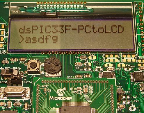
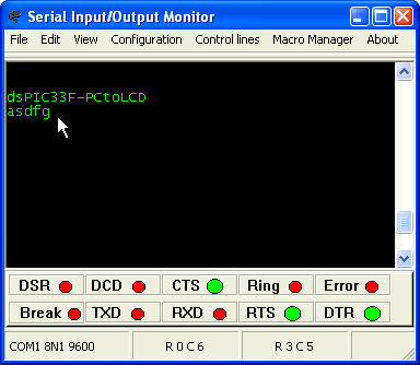
| LCD-USART De la USART al LCD. |
|
Y como consecuencia lógica e irrefrenable he montado una
combinación de dos de los ejemplos anteriores: La USART y el LCD. Este
ejemplo "oye" la USART y lo que recibe lo coloca en el PORTA, lo devuelve
por la misma USART como eco y lo coloca en el LCD en la segunda línea a
partir del carácter prompt ">". Si se completa totalmente esa segunda
línea del LCD la limpia y comienza de nuevo desde el segundo carácter de
la segunda linea del LCD. |
| main_lcd_usart.c | ||
/********************************************************************** * © 2008 PicManía By RedRaven * http://picmania.garcia-cuervo.net * * FileName: main_lcd_usart.c * Dependencies: p33FJ256GP710.h * Processor: dsPIC33F * Compiler: MPLAB® C30 v2.01 or higher * * When recive USART present in LCD * * C30 Optimization Level: -O1 * **********************************************************************/ #include "p33FJ256GP710.h" #include "lcd.h" _FOSCSEL(FNOSC_FRC); _FOSC(FCKSM_CSECMD & OSCIOFNC_OFF & POSCMD_NONE); _FWDT(FWDTEN_OFF); unsigned int flag_RECUSART; unsigned char CHAR_RECUSART; void __attribute__((interrupt, no_auto_psv)) _U2RXInterrupt(void){ CHAR_RECUSART = U2RXREG; flag_RECUSART =1; IFS1bits.U2RXIF = 0; } void __attribute__((interrupt, no_auto_psv)) _U2TXInterrupt(void){ IFS1bits.U2TXIF = 0; } void InitClock(void) { PLLFBD = 38; // M = 40 CLKDIVbits.PLLPOST = 0; // N1 = 2 CLKDIVbits.PLLPRE = 0; // N2 = 2 OSCTUN = 0; RCONbits.SWDTEN = 0; // Clock switch to incorporate PLL __builtin_write_OSCCONH(0x01); __builtin_write_OSCCONL(0x01); while(OSCCONbits.LOCK != 1) {}; } void InitUART2(void){ U2MODEbits.UARTEN = 0; // Bit15 TX, RX DISABLED, ENABLE at end of func //U2MODEbits.notimplemented; // Bit14 U2MODEbits.USIDL = 0; // Bit13 Continue in Idle U2MODEbits.IREN = 0; // Bit12 No IR translation U2MODEbits.RTSMD = 0; // Bit11 Simplex Mode //U2MODEbits.notimplemented; // Bit10 U2MODEbits.UEN = 0; // Bits8,9 TX,RX enabled, CTS,RTS not U2MODEbits.WAKE = 0; // Bit7 No Wake up (since we don't sleep here) U2MODEbits.LPBACK = 0; // Bit6 No Loop Back U2MODEbits.ABAUD = 0; // Bit5 No Autobaud (would require sending '55') U2MODEbits.URXINV = 0; // Bit4 IdleState = 1 (for dsPIC) U2MODEbits.BRGH = 0; // Bit3 16 clocks per bit period U2MODEbits.PDSEL = 0; // Bits1,2 8bit, No Parity U2MODEbits.STSEL = 0; // Bit0 One Stop Bit U2BRG = 240; // 40Mhz osc, 9600 Baud // Load all values in for U1STA SFR U2STAbits.UTXISEL1 = 0; //Bit15 Int when Char is transferred (1/2 config!) U2STAbits.UTXINV = 0; //Bit14 N/A, IRDA config U2STAbits.UTXISEL0 = 0; //Bit13 Other half of Bit15 //U2STAbits.notimplemented = 0; //Bit12 U2STAbits.UTXBRK = 0; //Bit11 Disabled U2STAbits.UTXEN = 0; //Bit10 TX pins controlled by periph U2STAbits.UTXBF = 0; //Bit9 *Read Only Bit* U2STAbits.TRMT = 0; //Bit8 *Read Only bit* U2STAbits.URXISEL = 0; //Bits6,7 Int. on character recieved U2STAbits.ADDEN = 0; //Bit5 Address Detect Disabled U2STAbits.RIDLE = 0; //Bit4 *Read Only Bit* U2STAbits.PERR = 0; //Bit3 *Read Only Bit* U2STAbits.FERR = 0; //Bit2 *Read Only Bit* U2STAbits.OERR = 0; //Bit1 *Read Only Bit* U2STAbits.URXDA = 0; //Bit0 *Read Only Bit* IPC7 = 0x4400; //Mid Range Interrupt Priority level, no urgent reason IFS1bits.U2TXIF = 0; //Clear the Transmit Interrupt Flag IEC1bits.U2TXIE = 1; //Enable Transmit Interrupts IFS1bits.U2RXIF = 0; //Clear the Recieve Interrupt Flag IEC1bits.U2RXIE = 1; //Enable Recieve Interrupts U2MODEbits.UARTEN = 1; //And turn the peripheral on U2STAbits.UTXEN = 1; } void putUART2(char c){ while ( U2STAbits.UTXBF); // wait while Tx buffer full U2TXREG = c; } void putsUART2(char *s){ unsigned int i=0; while(s[i]) // loop until *s == \0, end of string putUART2(s[i++]); // send the character and point to the next one } int main(void){ char mytext1[] = "dsPIC33F-PCtoLCD"; char mytext2[] = "> "; char *pText1=&mytext1[0]; char *pText2=&mytext2[0]; unsigned int nCHARS=0; TRISA = 0x0000; // All to output InitClock(); // This is the PLL settings InitUART2(); // Initialize UART2 for 9600,8,N,1 TX/RX Init_LCD(); // Initialize LCD // Send to serial putsUART2(mytext1); putsUART2("\r\n"); // Hellow World message home_clr(); puts_lcd(pText1,sizeof(mytext1)-1); line_2(); puts_lcd(pText2,sizeof(mytext2)-1); line_2(); cursor_right(); // Infinite Loop flag_RECUSART = 0; while(1){ if(flag_RECUSART==1){ flag_RECUSART=0; LATA = CHAR_RECUSART; // Lo que recibo vía UART2 lo pongo en el PORTA ... putUART2(CHAR_RECUSART); // ... lo devuelvo como eco ... lcd_data(CHAR_RECUSART); // ... y lo pongo en el LCD if(++nCHARS==15){ line_2(); puts_lcd(pText2,sizeof(mytext2)-1); line_2(); cursor_right(); nCHARS=0; } } }; } |
||
|
|
|
|
|
Nota: Esta página Web esta repleta de imágenes, textos, logotipos y demás material extraídos de los mas variados medios de los que no soy ni autor ni depositario de los correspondientes derechos de autor, uso y/o reproducción. Si Ud. es depositario de dichos derechos y desea que el material correspondiente sea eliminado de esta Web no dude en ponerse en contacto conmigo mediante e-mail y será inmediatamente retirado. Gracias. |
Esta página fue modificada el 07-08-2010 22:41:25